

AI 3D printing works best when you treat text-to-3D output as a draft mesh that still needs inspection, repair, and slicing. An STL download alone doesn’t prove that a model has printable walls, correct dimensions, or usable internal geometry.
I judge these tools by the usable geometry they produce, not the polish of their previews. A convincing render can hide defects that only appear after export.
The practical workflow starts with separating visual quality from physical printability.
Key Takeaways
I recommend treating generation, mesh repair, and print preparation as separate stages, even when one product offers all three.
- A textured model can look detailed while its underlying mesh contains little printable surface detail.
- Automated repair can close holes and correct topology, but it can’t reliably recover design intent or establish functional tolerances.
- The final acceptance test belongs in your slicer, at the intended size and with the intended printer profile.
For decorative objects, text-to-3D can provide a useful starting point. For dimension-critical components, conventional CAD remains the more dependable foundation.
What AI Text-to-3D Tools Actually Produce
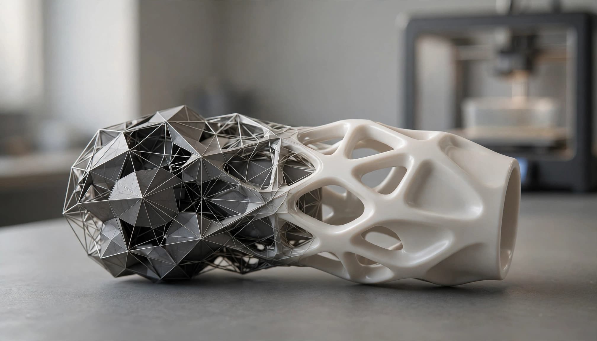
Surface Appearance Can Hide Missing Geometry
Most text-to-3D workflows generate polygon meshes rather than editable, dimension-driven CAD models. Those meshes can include textures that contribute heavily to their appearance.
For example, a normal map can suggest dents or grooves without putting those features into the printable surface. Converting that asset to STL won’t automatically turn its shading into physical detail.
I recommend inspecting the model with textures disabled before investing time in repair. Rotate it underneath and behind, too. Our coverage of AI-generated game asset workflows makes a related distinction: generated assets still need technical review before production use.
Organic Shapes Fit Better Than Precision Parts
Decorative sculptures, tabletop scenery, and stylized figures tolerate more interpretation than mechanical components. Their usefulness often depends on recognizable form rather than exact mating dimensions.
A replacement enclosure, threaded adapter, or snap-fit component has different requirements. Its dimensions and clearances must work together, and a prompt doesn’t establish those relationships.
My recommendation is to use generation for the exterior concept when appropriate, then build critical interfaces in CAD software such as FreeCAD. Repairing mesh errors won’t turn an approximate hole into a correctly specified bearing seat.
Choose Tools by the Repair Workflow
These recommendations are documentation-based, not results from a comparative printing benchmark. I would evaluate the complete path to a usable file before comparing generation speed.
Meshy Documents Print-Specific Checks
Meshy’s printing documentation describes a Print Check that reports watertightness, hole count, and non-manifold edges. Its Make Printable function addresses defects including open boundaries and degenerate faces.
Its export guidance also lists STL and 3MF among supported formats. Those are useful capabilities, but the presence of an export option doesn’t establish print readiness.
Tripo AI also offers text-to-3D and image-to-3D workflows. However, I wouldn’t rank either generator on preview quality alone. The meaningful comparison is how much usable geometry survives export and how much intervention it needs afterward.
Blender Provides an Independent Second Pass
Blender gives you direct access to the mesh rather than another generated interpretation of it. Its free 3D Print Toolbox extension adds print-oriented analysis, alignment, scaling, and export tools.
That separation matters because a generator’s own repair process may alter features you wanted to preserve. An independent mesh editor lets you inspect those changes.
I prefer a workflow with explicit handoffs: generator for shape creation, Blender for geometry inspection, and a slicer for manufacturing preparation. An integrated tool can shorten that sequence, but it shouldn’t remove those decisions.
Pick File Formats for Geometry, Not Appearance
Different formats preserve different information, so the best export depends on the next application.
| Format | What It Commonly Preserves | Printing Implication |
|---|---|---|
| STL | Triangulated surface geometry | Broad compatibility, but no standardized units or ordinary texture workflow |
| OBJ | Mesh geometry and optional material references | Useful for editing; linked texture files can complicate transfers |
| GLB | Meshes, materials, textures, and scene data | Useful for visualization, but slicer support varies |
| 3MF | Geometry, units, and potentially color or manufacturing data | Useful for printing workflows, with application-dependent support |
The takeaway is straightforward: changing formats doesn’t repair geometry. A broken OBJ can become an equally broken STL.
I would retain the original export and an editable working file before creating the printing copy. That gives you a recovery point if cleanup removes details or merges separate components.
For Blender users, its STL export documentation describes options such as exporting only selected objects. That matters when your scene also contains reference meshes or alternate versions.
Finally, distinguish a geometry file from a slicer project. A 3MF project can contain application-specific preparation data, but you shouldn’t assume every program will interpret that data identically.
Prompt for a Printable Starting Shape
Good prompting can reduce avoidable cleanup, although it can’t guarantee valid topology.
I recommend describing the object’s physical structure alongside its appearance. Broad contact surfaces, substantial limbs, and connected decorative elements generally give you a more manageable starting point than floating accessories and needle-thin projections.
For a figurine, identify whether accessories should connect to the body or become separate parts. For a display object, request a stable base rather than assuming the generator will create one.
Also distinguish surface decoration from actual relief. Painted panel lines won’t become engraved channels merely because the preview looks three-dimensional.
If text-only generation struggles with pose or silhouette, an image-first workflow can provide more visual direction. Our OpenArt pose-reference overview covers tools relevant to preparing that reference image, not manufacturing-ready geometry.
Keep the reference focused on one object with visible proportions. Busy backgrounds and obscured surfaces introduce additional ambiguity.
Even then, the generated backside and hidden surfaces still need inspection. A clearer reference reduces uncertainty; it doesn’t eliminate reconstruction errors.
Inspect Geometry Before You Repair It
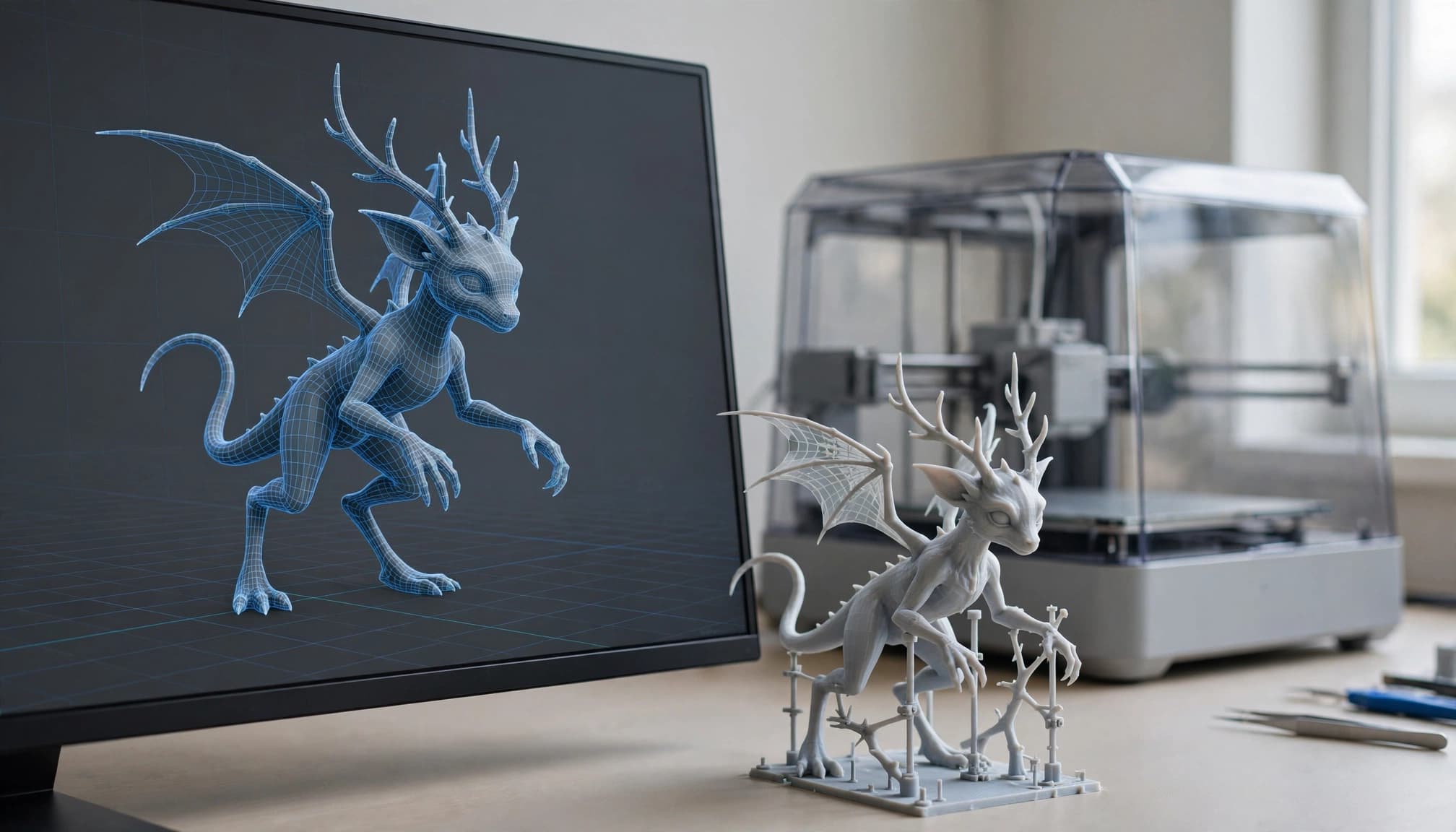
Find Open Boundaries and Incorrect Normals
For a conventional closed printable solid, each surface edge should connect to exactly two faces. An edge with one face indicates an opening; an edge shared by more than two faces is non-manifold.
Blender’s mesh diagnostic documentation explains these checks alongside inconsistent normals, intersections, and thickness problems.
Normals describe surface orientation. Inconsistent normals can confuse how software interprets inside and outside.
However, an intentional opening in an object isn’t necessarily an open mesh boundary. A cup can have an open top while its inner and outer walls form a completely closed material volume.
Separate Intersections From Unwanted Fragments
Intersecting surfaces deserve inspection, but they don’t all require the same fix. Some slicers can handle overlaps; others may interpret them in unexpected ways.
I would examine whether overlapping parts should form one solid, remain separate, or merely touch. Those are design decisions that an automatic repair function can’t infer reliably.
Also look for disconnected fragments and internal surfaces. A small island might be generation debris, but it could also be an intended accessory.
Repair should preserve the intended material volume. A lower error count is a poor trade if cleanup removes a required opening or fuses moving parts.
Repair Defects in a Controlled Order
I recommend repairing a duplicate so you can compare the result against the original. Avoid stacking several automatic operations without inspecting intermediate changes.
- Set the intended dimensions and identify separate components. Establishing size helps you interpret merge distances and thickness checks.
- Remove confirmed debris and loose geometry. Keep intended accessories or disconnected parts that you plan to print separately.
- Correct topology and surface orientation. Merge appropriate vertices, address open boundaries, and recalculate outward normals where needed.
- Run the analysis again, then inspect the repaired shape visually. Remaining errors may require manual editing rather than another automatic pass.
Meshy’s Blender cleanup documentation follows a similar pattern: analyze, run Make Manifold, optionally remove small pieces, and analyze again. It also directs unresolved problems to manual editing.
That sequence matters because operations have side effects. Filling a boundary can cap an intended passage. A generous merge distance can collapse nearby features.
Prusa’s model-repair guidance provides additional context on repairing corrupted printing meshes. The practical principle is to match the repair to the defect rather than treating every warning as interchangeable.
If you use voxel remeshing to rebuild a difficult surface, expect a detail trade-off. Coarse settings can erase small features or merge nearby surfaces, so compare the reconstructed mesh before accepting it.
Set Scale and Wall Thickness Before Slicing
Physical Size Changes What Survives
A mesh can remain watertight at any scale while becoming physically unsuitable as you shrink it. Thin fingers, antennae, and embossed lettering are common trouble areas.
That makes thickness analysis meaningful only in relation to the intended dimensions and printing process. There isn’t one universal minimum wall thickness for every material, orientation, and printer.
I would set the overall size before judging fragile details, then inspect those features individually. A model that works as a display sculpture may need substantial redesign as a miniature.
For API workflows, unit conversion deserves equal attention. Meshy’s documented Resize input uses meters, so 100 mm corresponds to 0.1 m.
Automatic Thickening Has Limits
Meshy’s Repair Printability API documents an important condition: it thickens walls only when more than 5% of the surface is too thin for the selected printer. It also retains the model’s original scale.
That threshold means a small but fragile feature can still deserve manual attention. Passing an automated operation isn’t evidence that every projection meets your requirements.
The documentation also distinguishes size-aware repair using printer type, print size, or both. I wouldn’t treat a generic repair operation as a substitute for analysis at the actual production size.
Where thickening would damage the design, splitting the model or changing its orientation may be more sensible than adding material everywhere.
Validate the Export in a Slicer
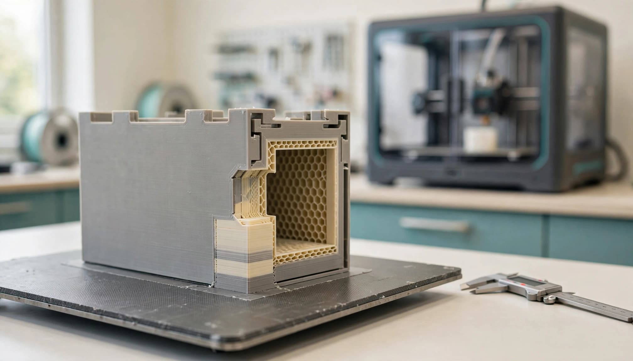
Inspect Layers, Not Just the Preview
Import the repaired file into a slicer such as PrusaSlicer and confirm its displayed dimensions. Then select the intended printer and material profile before slicing.
I recommend moving through the layer preview around thin features, internal openings, and transitions between disconnected regions. Look for missing sections, unexpected filled cavities, and features that begin without support beneath them.
A successful import only proves the application accepted the file. The sliced toolpaths reveal what the printer will attempt to build.
Also compare the exported file with the working model. Exporting the wrong selection or an earlier version can undo otherwise careful preparation.
Match Supports to the Printing Process
FDM and resin printing impose different constraints. For FDM, consider bed contact, overhangs, bridging, and the strength implications of layer orientation.
For resin, examine islands, support placement, and hollow sections. Closed cavities can trap liquid resin, so hollow designs need appropriate drainage and cleaning access.
Supports don’t repair a mesh, and watertight geometry doesn’t eliminate support requirements. Treat both as necessary decisions.
My final digital acceptance criteria are simple: correct dimensions, the intended material volume, and plausible layers under the chosen profile. A physical test print is still necessary before relying on fit or mechanical performance.
Decide When Repair Costs More Than Remodeling
The generator’s subscription is only one part of the cost. Cleanup time, repeat generations, failed prints, and finishing work also affect whether the workflow makes sense.
I would continue repairing when the overall shape is useful and the defects are local. I would remodel when functional surfaces remain approximate or each repair damages another required feature.
A high polygon count doesn’t settle that decision. Dense geometry can preserve detail, but it can also make editing slower without improving the printed result.
Also avoid paying for unrelated capabilities. Our AI world-building tools guide covers scene and environment workflows, which solve a different problem than producing one closed printable object.
For confidential product concepts, cloud generation also introduces a data-handling decision. A local repair stage doesn’t undo an earlier upload.
Finally, keep the application proportionate to the evidence. I wouldn’t recommend an unvalidated generated mesh for load-bearing, medical, or other safety-critical use. Visual plausibility and automated topology repair provide no proof of mechanical suitability.
FAQ
Can AI-Generated STL Files Be Printed Directly?
Some can, but the file extension doesn’t establish readiness. Import the model at its intended size, inspect its geometry, and review the sliced layers. Even a closed mesh can contain fragile details, unsuitable overhangs, or incorrect dimensions that prevent a useful print.
Does Converting GLB or OBJ to STL Fix Errors?
No. Conversion changes the file representation, not necessarily the underlying surface. Holes, intersections, and disconnected fragments can survive conversion. Materials and textures can also disappear because standard STL workflows preserve surface geometry rather than the full appearance of the original asset.
Is Blender Enough for Mesh Repair?
Blender and its 3D Print Toolbox can handle many inspection and repair tasks. However, difficult geometry can still require manual reconstruction. For precise interfaces and dimension-driven parts, CAD software may be more appropriate than trying to repair an approximate generated mesh.
Does a Watertight Mesh Guarantee a Successful Print?
No. Watertightness addresses whether the surface encloses a volume. It doesn’t establish adequate thickness, correct dimensions, suitable supports, or material performance. You still need process-specific preparation and, where fit or strength matters, physical validation before relying on the finished part.
Further Topics to Explore
For a deeper technical follow-up, three practical subjects build on this workflow:
- Blender 3D Print Toolbox: diagnosing and repairing non-manifold meshes without losing detail.
- STL versus 3MF: preserving scale, color, and slicer settings during file handoffs.
- AI-generated miniatures: wall thickness, model splitting, and support planning for resin printing.
Make Printability the Acceptance Standard
AI 3D printing is useful when generation reduces modeling effort without creating a larger repair burden. The strongest workflow keeps geometry validation separate from visual approval.
I recommend preserving the original mesh, repairing deliberately, and judging the final export in the slicer. Use CAD when the part requires controlled dimensions or functional interfaces.
A polished preview can justify further work. A model earns its place on the build plate through its geometry and preparation.